Wednesday, 11 April 2012

AIRBUS A 320


Airbus  is an aircraft manufacturing subsidiary of EADSAirbus employs around 52,000 people at sixteen sites in four European Union countries: France, Germany, the United Kingdom and Spain. Final assembly production is at Toulouse (France),Hamburg (Germany), Seville (Spain) and, since 2009, Tianjin (People's Republic of China).Airbus has subsidiaries in the United States, Japan, China and India.The Airbus  family consists of short- to medium-range, narrow-body, commercial passenger jet airliners manufactured by Airbus 


ÒThe family includes the A318A319A320 and A321
ÒThe aircraft family can accommodate up to 220 passengers and has a range of 3,100 to 12,000 km (1,700 to 6,500 nmi), 
ÒThe first member of the A320 family—the A320—was launched in March 1984, first flew on 22 February 1987, and was first delivered in 1988.
ÒThe A320 family pioneered the use of digital fly-by-wire flight control systems, as well as side-stick controls, in commercial aircraft
ÒUp till now 4858 A-320’s are manufactured & 4765 are in service. And 3255  aircrafts orders is placed. The fastest selling aircraft of the world
ÒOn 1 December 2010, Airbus officially launched the new generation of the A320 family with the A320neo "New Engine Option”


Flight deck equipped with
ÒElectronic Flight Instrument System (EFIS)
Òside-stick controllers
Ò Electronic Centralised Aircraft Monitor (ECAM)
ÒElectronic Flight Control System (EFCS)
ÒFlight Management Systems (FMS)
ÒCentral Fault Display System (CFDS)
ÒThe Electrical Flight Control System (EFCS) provides :
 Safety improvements (stall / windshear / overstress /
Òoverspeed protection)
Òequipped with full flight envelope protection  was a new experience for many pilots


:: DC Power Supply ::

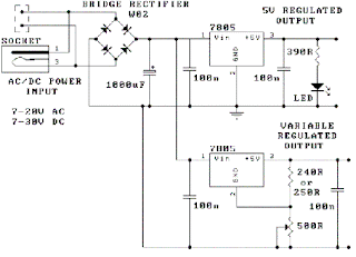
This project provides a simple DC Power Supply from an input power supply of 7-20 V AC or 7-30V DC.

Two DC voltage outputs are available; one is a fixed regulated 5V for TTL use. The other output is variable from 5V upwards. The maximum output voltage depends on the input voltage. The specified maximum input DC voltage to the regulator is 35V. The minimum input voltage must be 2 volts higher than the regulated output voltage.


Circuit Diagram:


DESCRIPTION:
 The DC Power Supply circuit is based around the 7805 voltage regulator. It has only 3 connections (input, output and ground) and itprovides a fixed output. The last two digits of the part number specify the output voltage, eg. 05, 06, 08, 10, 12,15, 18, or 24.The 7800 series provides up to 1 amp load current and has on-chip circuitry to shut down the regulator if any attempt is made to operate it outside its safe operating area.A variable 500 ohm potentiometer is used to vary the output voltage from a minimum of 5V up to the maximum DC voltage depending on the input voltage. It will be about 2V below the input DC voltage.)The second 7805 has a resistor divider network on the output. A variable 500 ohm potentiometer is used to vary the output voltage from a minimum of 5V up to the maximum DC voltage depending on the input voltage. It will be about 2V below the input DC voltage.)


:: Digital Voltmeter ::

This digital voltmeter is ideal to use for measuring the output voltage of your DC power supply. It includes a 3.5-digit LED display with a negative voltage indicator.

It measures DC voltages from 0 to 199.9V with a resolution of 0.1V. The voltmeter is based on single ICL7107 chip and may be fitted on a small 3cm x 7cm printed circuit board. The circuit should be supplied with a 5V voltage supply and consumes only around 25mA.


Circuit Diagram:


COMPONENTS:

DESCRIPTION:

 The use of 7805 5V voltage regulator is highly recommended to prevent the damage of ICL7107, 7660 ICs and to extend the operating voltages. 220 Ohm resistor should be connected to the PIN 4 on the first LED display.The voltmeter can also be configured to measure different voltage ranges and display higher voltage resolution. Replacing 1M with 100K resistor will allow to measure 0 - 19.99V voltages with 0.01V (10mV) accuracy.


Tuesday, 29 November 2011

FINAL YEAR PROJECT


Avionics engineering deals with the specialization of electronics of an aircraft. It is the back bone of modern aircrafts. The hi-tech auto pilot system, highly effective navigation, guidance and reliability of flight control system are the few examples that are making flights safer. The project which we came up with is “MOCK UP PLANE”. Actually mock up is called “PROTOTYPE” ” which provides a least part of the functionality of a system. This project is a scaled down model of an aircraft which is fixed on the top of a vertical rod. This model of aircraft is used to demonstrate the primary movements of an aircraft i.e. roll, pitch and yaw. These movements of the aircraft will be demonstrated with the help of wireless remote control and all the basic parameters of an aircraft will be shown on graphical display.


To design a Mock Up Plane which shows three primary movements of an aircraft.

  1. Design Mock-up plane.
  2. To control the movements of aircraft using wireless control.
  3. Show angles of the movements on graphical display.


         HARDWARE AND SOFTWARE LIST(FINAL)

              HARDWARE
1.    Mechanical Structure.
2.    Servo Motors.
3.    Airplane Model.
4.    Wireless Remote.
5.    Controllers etc.
SOFTWARE
1.    Lab View.


         REFERENCES


1.      Instrument Flying Handbook. U.S. Government Printing Office, Washington D.C.: U.S.
2.      Scott, William B. (27 November 2006), "Morphing Wings", Aviation Week & Space Technology
3.       Jesberger, Lee A., "Mock Ups", Pro Woodworking Tips, 2006.
4.      Model Aircraft Aerodynamics, by Martin Simons, Argus, Watford, Herts, England, 1978
5.      Model Airplane Design and Theory of Flight, by Charles Hampson Grant, Jay Publishing Corporation, New York, 1941
6.      RCadvisor′s Model Airplane Design Made Easy, by Carlos Reyes, RCadvisor.com, Albuquerque, New Mexico, 2009.